
Triaging a nocrank condition and testing a starter motor Hagerty Media
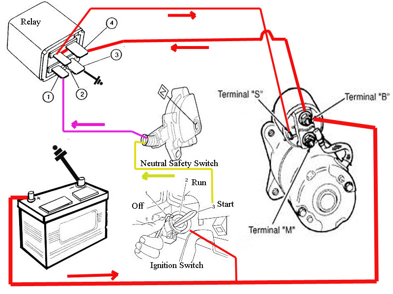
In this video I show how to wire a starter relay, starter solenoid, and neutral safety switch on an engine. I also explain how to bypass the solenoid if needed. This style starter circuit.
Motor Starter Schematic Manual EBooks 3 Phase Motor Starter Wiring Diagram Pdf Cadician's
A starter motor diagram is a visual representation of a car's starter motor assembly, outlining various parts of starting system including the starter wiring, and starter control circuit. It is a useful tool for understanding how the starter motor works, identifying issues, and carrying out repairs. Parts of a Starter Motor
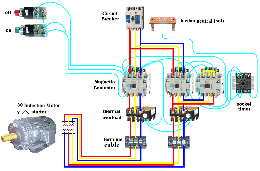
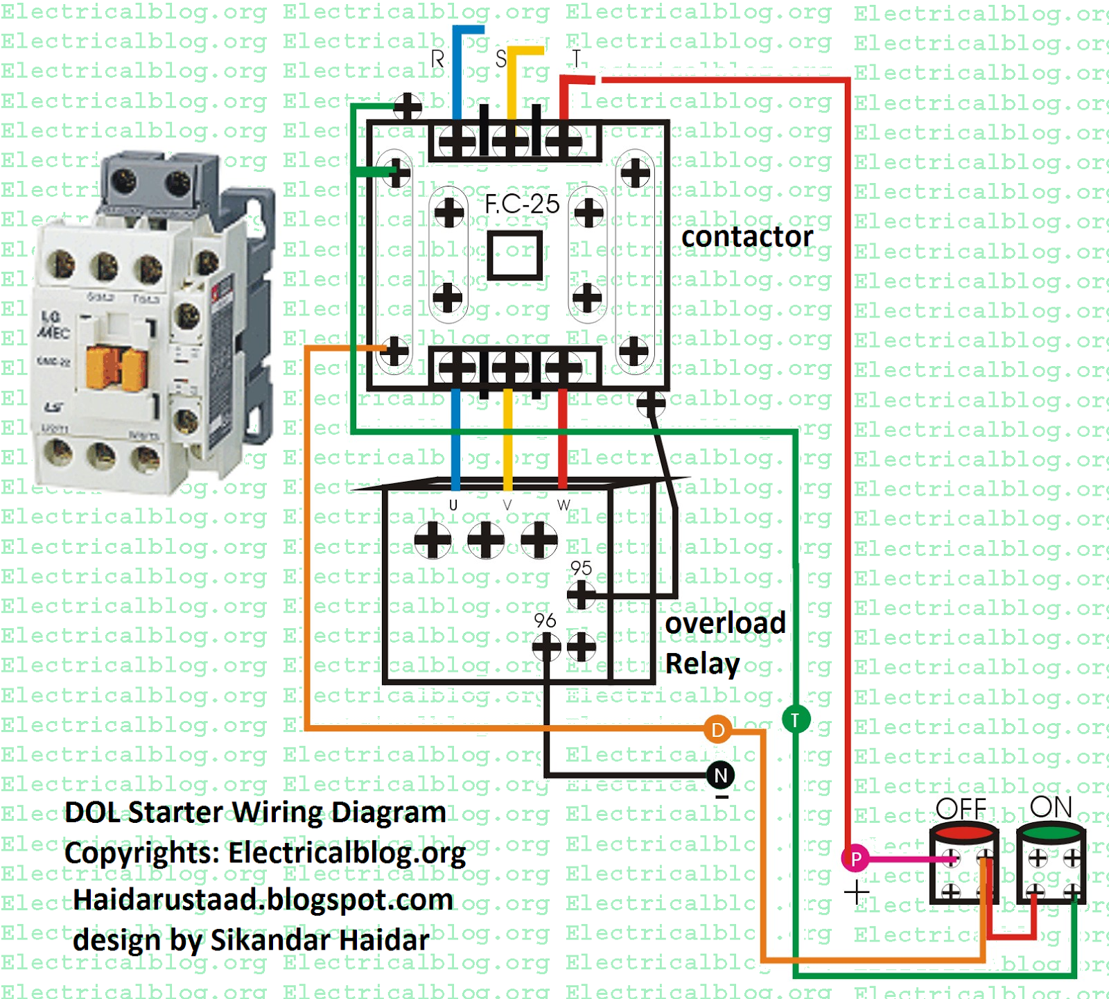
Wiring DOL Starter Motor (Star Delta) Elec Eng World
is a typical wiring diagram for a three-phase mag-netic starter. Figure 1. Typical Wiring Diagram Line diagrams show circuits of the operation of the controller. Line diagrams, also called "schematic" or "elementary" dia-grams, show the circuits which form the basic operation of the controller. They do not indicate the physical relation-
Starter Switch Wiring Diagram
0:00 / 11:41 HOW to test a STARTER MOTOR, DIY wiring diagram, and troubleshoot EXPLAINED Craft Customs 79K subscribers Subscribe Subscribed 149K views 2 years ago just an idea on how a.
Motor Starter 8538 Wiring Diagram Collection
If you don't see what you're looking for, please ask. Springer Controls has a certified UL508A panel shop to build custom starters and control panels up to 500V. For any custom options like HOA (Hand-Off-Auto) starters, pilot lights, control transformers, or volume purchases, please contact us at 888-357-2138.
V Motor Starter Wiring Diagram vascovilarinho
Understanding the basics of the 12 Volt Starter Motor Wiring Diagram is the key to creating a successful electrical system from start to finish. To begin, the starter motor wiring diagram requires the battery, starter solenoid, and the starter motor itself. The diagram also includes various switches, fuses, and wiring connections needed to.
Electric Motor Starter Wiring Diagram
Starter Motor. The car's starting system works by converting electrical energy into mechanical energy to make the engine run. A starter motor and solenoid are tightly integrated pairs and the heart of the starting system. It is used to turn on the engine, without it, the engine isn't turning over and the car won't start.

Wiring Diagram For Electric Motor Starter
First, you should connect the battery to the starter terminal. Then, connect the starter terminal to the ignition switch. Afterwards, connect the ignition switch to the starter relay. Finally, connect the starter relay to the starter motor. By following all of these steps, you should have a successful 12 volt starter motor wiring setup that can.

Bosch Starter Wiring Diagram Wiring Diagram
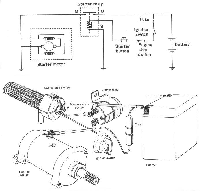
Starting system simplified diagram. As we mentioned, the starter motor requires very high electric current to turn over the engine. That's why it's connected to the battery with thick cables (see the diagram).

Powermaster Starter Wiring Diagram
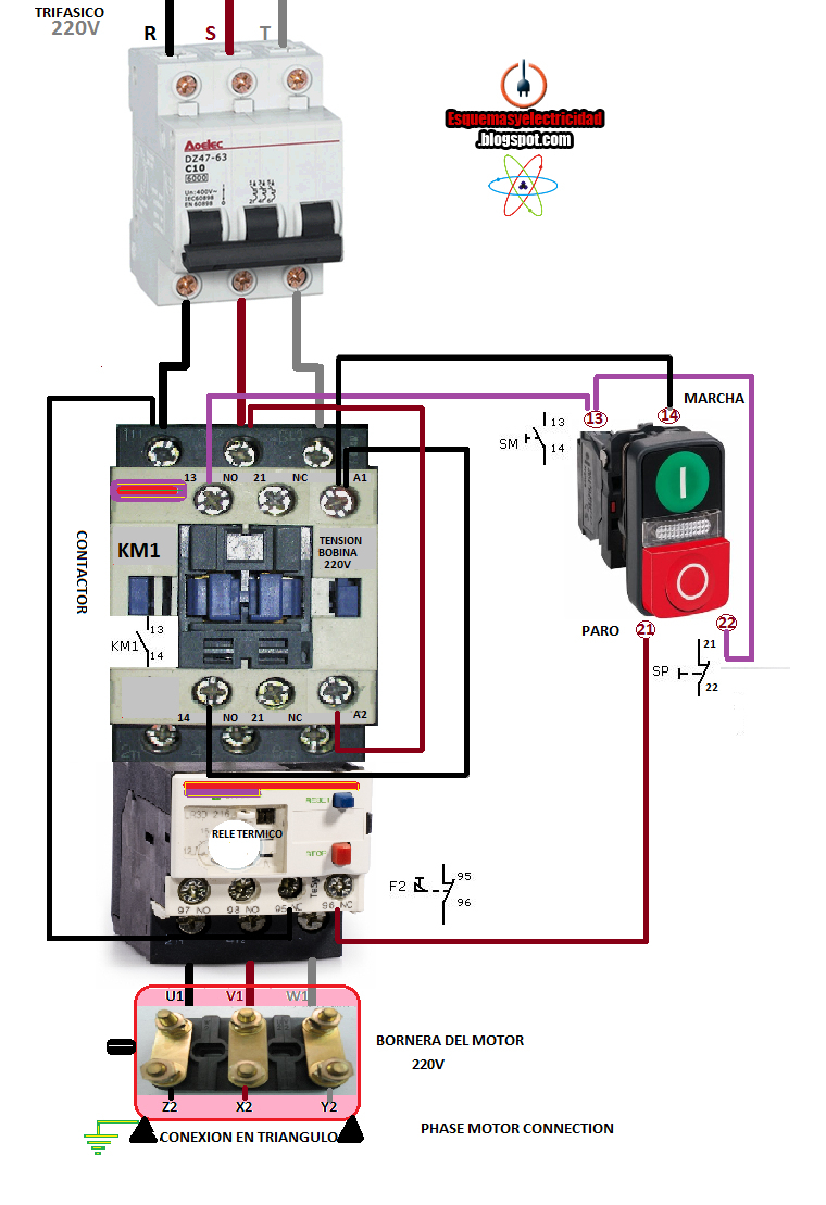
The following diagram depicts 3-phase non-reversing motor control with 24 VDC control voltage and manual operation. We will use a contactor, an auxiliary contact block, an overload relay, a normally open start pushbutton, a normally closed stop pushbutton, and a power supply with a fuse.

220V Single Phase Motor Wiring Diagram Wiring Diagram
Understanding the Starter Solenoid Wiring Diagram Starter Solenoid Wiring Diagram ples of electromagnetism in its work. When the ignition key is turned on, it sends an electrical signal to the solenoid, which then engages the starter motor and cranks the engine.
Starter Motor Circuit
This video will EXPLAIN how a three wire motor starter circuit works, show wiring diagrams of the circuit in each stage of the process and show examples of t.

Wiring Diagram For Ford Starter Relay
At its most basic level, a starter motor relay wiring diagram consists of symbols and lines that represent the different electrical components. These symbols can include relays, switches, motors, and the battery. The lines represent the electrical connections between these components.
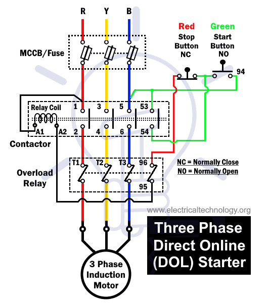
What is DOL Starter? Direct Online Starter Wiring and Working
We can stop the motor by pressing the stop switch. If the load on the motor exceeds its rated capacity, the overload relay signals and trips the contactor C2 and the motor trips. The wiring diagram of the Direct online motor starter is given below. The motor draws a large current, and it starts reducing when the motor attains its base speed.

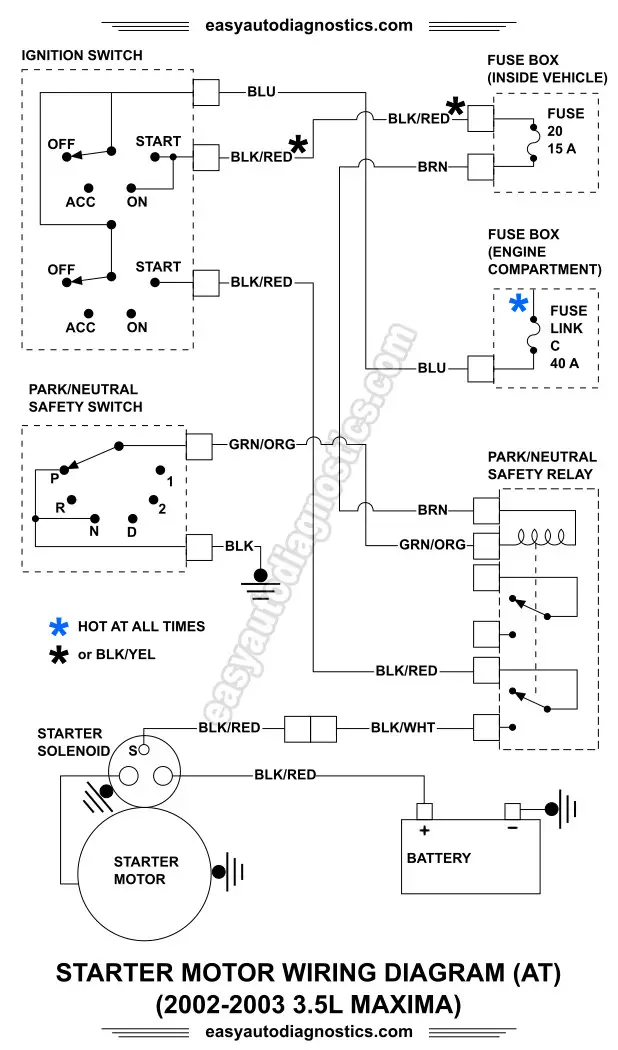
Starter Motor Wiring Diagram
2.8K Share 195K views 1 year ago Learn how your vehicle's starter motor and ignition system circuit work, including how the ignition switch, relay and safety gearshift are wired to kick start.
Starter Motor Wiring Diagram Wiring Diagram
Definition of Starter Motor. A starter motor or starting motor, or cranking motor, is a direct current motor that cranks the engine for starting. Cranking the engine means rotating the crankshaft by applying torque on it so that the piston may get reciprocating motion.. The starting motor is mounted on the engine flywheel housing. It is a series wound and is made to run at low voltages with.