
House Wiring Switchboard Size
Download EdrawMax Edit Online What is Electrical Switch Board? An electric switchboard is a device that directs electricity from one or more sources of power supply. In Switch Board, there are switch available to operate electrical appliances individually.

Electrical Switchboard Connection Wiring In Hindi
This diagram shows how to make switchboard wiring. In this diagram, we explain how to make a switch board wiring very easily. First, we need to connect the phase line to all switches and sockets, lights, and fan regulators. Then input the neutral line to the socket and ceiling fan and light.

wiring 240v switchboard for multiple sockets Google Search Distribution board, House wiring
Eaton's CMP switchboard combines all three components of a service entrance application into a single cell, including a main service compartment, a utility metering section and the distribution feeders, providing the most flexible and compact footprint for the entire service entrance switchboard. Application Description Eaton's CMP switchboard is
Switch Board Connection Circuit Diagram See More on SilentTool Wohohoo
Sample connection diagram CAN SWITCH BOARD V3 +12V GND CAN L CAN H twisted pair ECU / PMU / ADU CAN BUS S1 S2 L1 L2 +12V +12V SGND A1 +5V. The CAN (Control Area Network) bus was developed to communicate between devices in automotive environments. Its construction is very simple (only two wires) and its immunity to interference is very high.

Electrical Diagram For Switch
How To Wire a Switchboard (Part 1) sparkydave 21.4K subscribers Subscribe Subscribed 1.9K Share 150K views 4 years ago Advanced Electrical Skills How to fit off essential components of a.
Switch Board Connection Diagram Sales USA, Save 48 jlcatj.gob.mx
Electrical Switch Board Connection Diagram having a Fuse, Switches, Sockets, Indicator, and Fan Regulator. You will see here that all are marked with a prope.
12 modular switch board connection really ।। switch board wiring YouTube
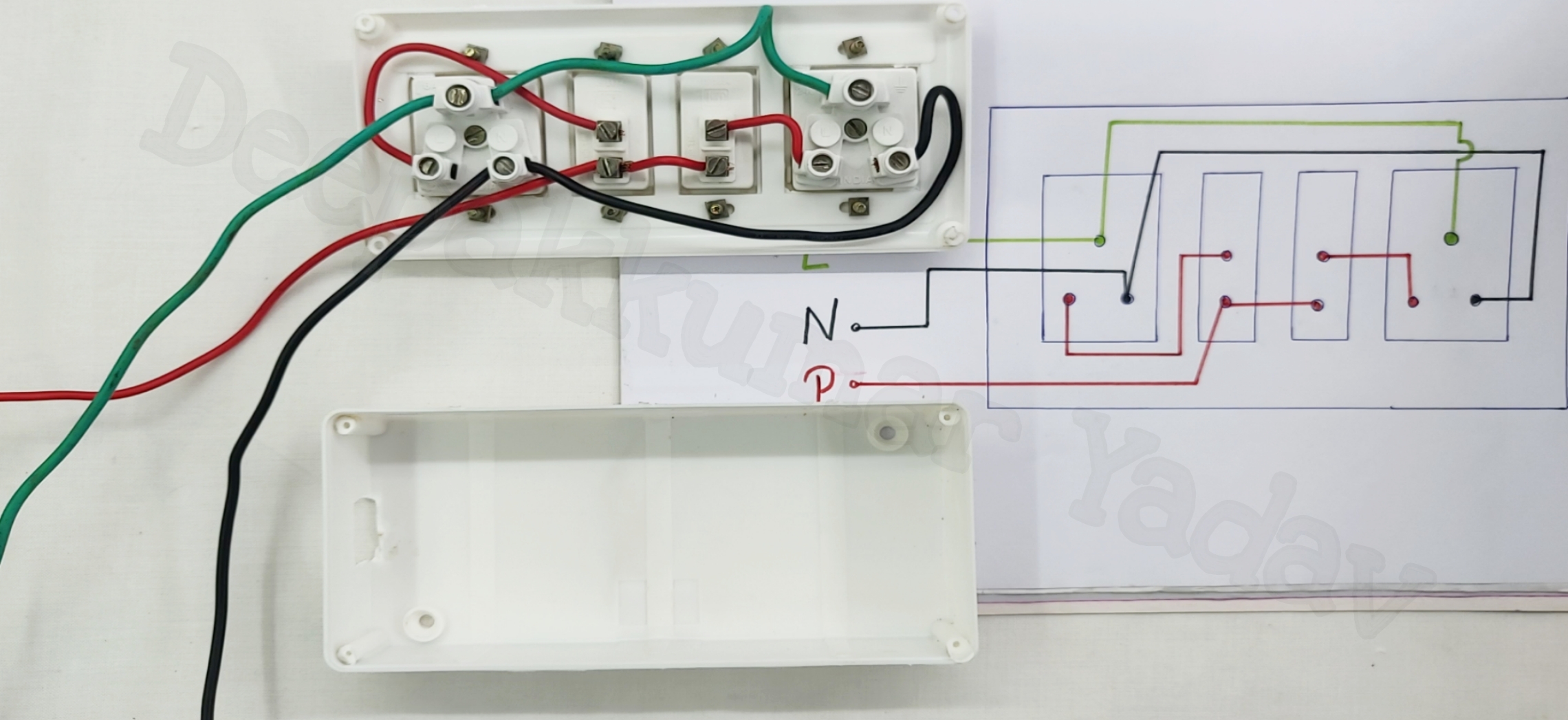
#BEEEWorks #Electricalwork #wiring Hello Friends ! Welcome back to our channel. I hope this video may helps you 😊🔴 Red wire = Phase ⚫ Black wire =.
electrical switch board connection diagram Wiring Diagram and Schematics
The following diagram illustrates accepted NEMA phase arrangements. Buses are mounted within the frame. Horizontal bus bars are used to distribute power to each switchboard section. Vertical bus bars are used to distribute power via overcurrent devices to the load devices. Bus bars are made of tin-finished aluminum or silver-finished copper.

Extension Switch Board Wiring Connection Diagram It ' S Electrical YouTube
This diagram shows how to make a switch board connection. In this circuit, we use a fuse, an indicator light, two switches, and two power sockets. First, we need to input the phase line connection to all component phase terminals, then need to input the neutral connection to the neutral point, and lastly input the earthing connection to the power sockets earth terminal. Now this circuit is.
single switch board connection diagram Wiring Diagram and Schematics
Switch box wiring or switchboard wiring is a common wiring arrangement used in most house electrical wirings or switchboards. The given circuit is a basic switchboard wiring for a light switch (one lamp controlled by one switch) and 3 pin plug socket with control switch. How to wire up a switchboard

How to make Electrical Switch Board Connection Diagram Switch Board Wiring YouTube
https://toolsreview.us/ Electric Board Wiring Connection ,socket , switch Indicator lamp,fuse,fan point,lighting point 7 way BoardPLEASE SUBSCRIBE MY NEW CHA.

Wiring Mcb Changeover Connection Diagram Wiring Diagram Schemas
A switchboard is a component of an electrical distribution system which divides an electrical power feed into branch circuits while providing a protective circuit breaker or fuse for each circuit in a common enclosure.
Switch Board Connection Diagram Sales USA, Save 48 jlcatj.gob.mx
ELECTRICAL SWITCH BOARD WIRING DIAGRAM Switch box wiring or switchboard wiring is a common wiring arrangement used in most house electrical wirings or switchboards. The given circuit is a basic switchboard wiring for a light switch (one lamp controlled by one switch) and 3 pin plug socket with control switch. How to wire up a switchboard

Switch Board Wiring Connection 5 in 1 // TWO TYPES WIRING CONNECTION YouTube
Example of MV switchgear wiring diagram. 1. The basics of MV switchgear. When we say "medium voltage" or just "MV" switchgear, we refer to a switchgear with "primary" equipment which operates at medium voltage level, typically at or close to 6 kV, 10 kV, 20 kV, and 35 kV in Europe. These are phase to phase, or "line" values of.

Electrical Extension Board Connection Diagram and Wiring ETechnoG
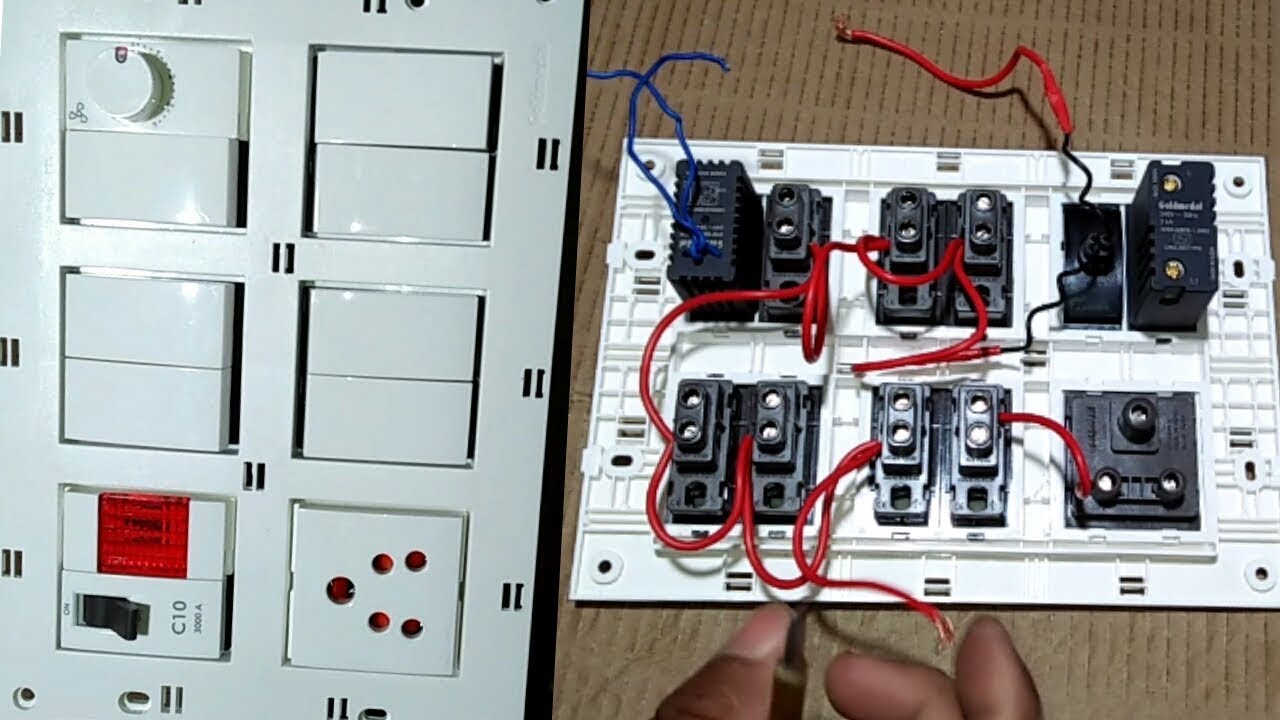
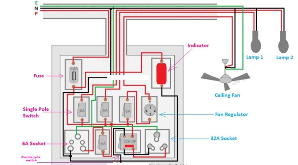
Components used to Make the Switch Board. Fuse; I n the above wiring diagram we have connected a 63A fuse in series with the main input phase supply In this diagram the total load of the circuit is 56 A(calculated by the total of all switches ratings). So 63A is enough for this switchboard. But don't use the fuse having a current rating of.
ELECTRICAL SWITCH BOARD CONNECTION electrician trade theory
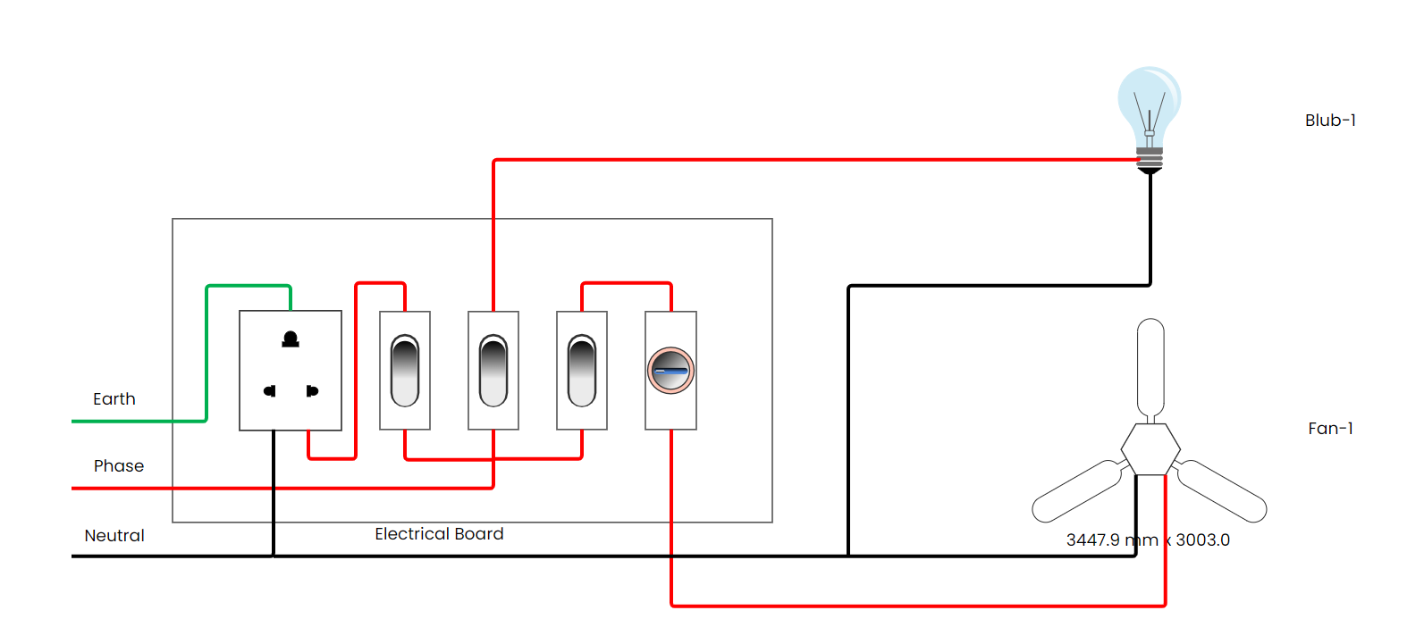
This diagram shows how to connect an electrical switchboard wiring diagram. In this circuit, we use a 3-pin power socket, some switches, 2 light holders, a ceiling fan, a fan regulator, an indicator light, etc. If you want to see clear animation for how to connect this circuit very easily please check our video in the below link.