
Metall detektor med 555 Liten kunnskap
NAMA : FEBRIAN GAVRILA INIM : 190491100079KELOMPOK : 20PRAKTIKUM : SISTEM DIGITALNB : suaranya kurang jelas dan bergema Semoga video diatas bermanfaat bagi k.

Skema Lampu Strobo Ic 555 Ruang Ilmu
A dual version of the timer is also available. The 556 is two independent timers on a single 14-pin DIP chip. Pin placement is shown in the illustration. The 555 timer IC has been around now for quite some time and the list of potential uses for this device appears to be endless. This article contains a few.
Electro True Story Detektor Metal Sederhana Menggunakan IC NE 555
4) Solder the Buzzer on the veroboard. 5) After that, solder the +ve pin of a 10uF capacitor wit pin 6 of the IC and the -ve pin with the +ve of the buzzer. 6) Place the 555 timer IC in the IC socket. 7) Solder the 100mH inductor coil between the 2.2uF capacitor and pin 3 of the IC. 8) After that, connect the battery clip between pin 1 and pin.
Belajar Elektronika Skema Rangkaian Running LED Menggunakan IC 555 dan
the circuit is realized by utilizing the high input impedance of trigger pin of the IC 555. When the IC is triggered by the induced voltage of human body the output goes high for a time determined by R1 and C1. The transistor is used to drive the relay. The relay contacts can be used to drive the load like bell, motor , lights etc.

Senapan Kejutan Listrik Menggunakan 555 schematic diagrams, repair
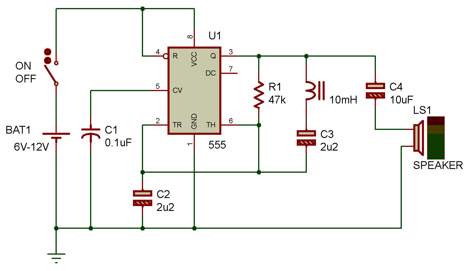
The inductor of 10mh in the above circuit serves the purpose of metal detection and 555 serves the multivibrator section of the above circuit. The IC 555 vibrates at specific frequency in normal state which in turn drives the output buzzer for the purpose of indication. You can also add a LED along with the buzzer for indication provided.

Share IC TIMER 555
Ini digunakan dalam detektor Pulsa. Ini dapat digunakan untuk membuat Sakelar Timer. Demikian materi mengenai apa itu IC 555, Fungsi, Cara Kerja, Pin out dan penggunaan IC 555 pada kehidupan sehari - hari. Semoga apa yang tim Kelasplc.com bagikan ini dapat memberikan Anda manfaat.

Handoko tehnik MERAKIT DETEKTOR LOGAM EMAS DGN IC NE 555... YouTube
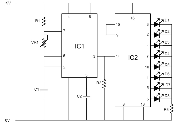
Rangkaian Detektor Emas. Here the very simple and easy build gold detector circuit. The circuit capable to sense gold or metal or coins from a distance of about 20cm, depending on the size of the object to detect. The circuit oscillates at about 140kHz and a harmonic of this frequency is detected by an AM radio.
skema Polarity protection pwm ic 555 untuk box mod diy
Skema detektor emas IC 555 menggunakan prinsip getaran untuk mendeteksi keberadaan emas. Ketika skema ini berada di dekat logam emas, osilator akan terganggu dan menghasilkan perubahan output yang dapat terlihat atau terdengar melalui sinyal yang dihasilkan. Semakin dekat detektor ini dengan logam emas, semakin kuat sinyal yang dihasilkan.
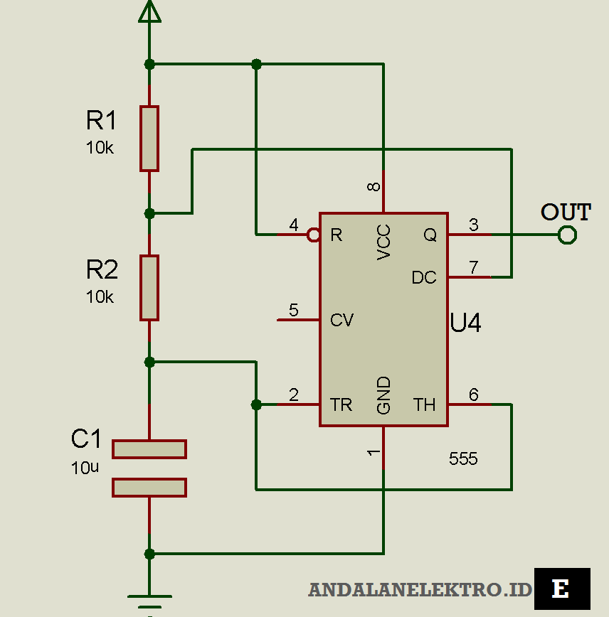
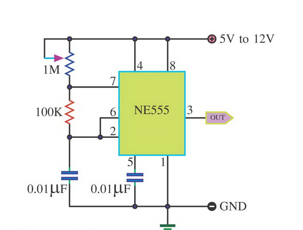
Prinsip Kerja Rangkaian IC 555, Rumus Frekuensi dan Duty Cyclenya
Dari beberapa aplikasi dari IC NE55 pada kesempatan kali ini saya akan menjelasklan cara kerja atau prinsip kerja dari rangkaian timer selama 5 menit. Rangkaian ini memeiliki dua elemen timing yaitu VR1 DAN C1,di sini kita dapat merubah durasi waktu yang kita inginkan dengan mengubah nilai dari kedua komponen tersebut.

Rangkaian Saklar sentuh Berbasis IC 555 Koleksi Skema Rangkaian
Contents Skema Detektor Emas ic 555 Komponen dalam Skema Detektor Emas ic 555 Fitur Skema Detektor Emas ic 555 Faktor yang Jangkauan Pendeteksian Skema Detektor Emas ic 555 Mineralisasi Tanah (dan batuan) Karakter Target (Benda Emas) Sensor Detektor Logam (Koil) Interferensi Eksternal Teknologi Detektornya Kesalahan Pengaturan Informasi Lengkap tentang Skema Detektor Emas ic 555, Penambang […]

Skema Lampu Strobo Ic 555
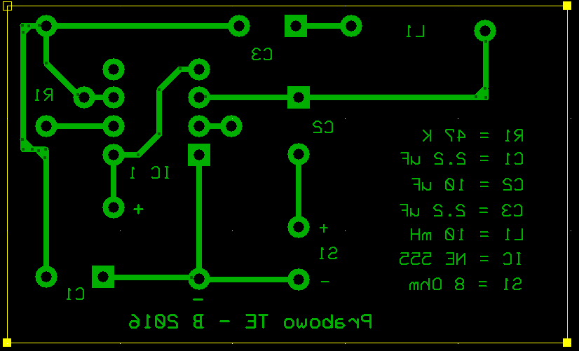
Skema metal detektor,pendeteksi logam,rangkaian metal detektor,metal detektor IC 555,cara membuat metal detektor
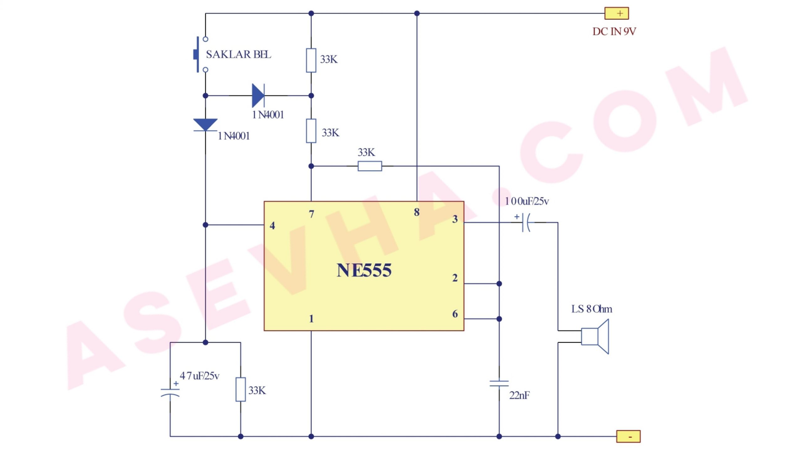
Skema Bel Pintu 2 Nada dengan IC 555 Tutorial, Desain & Hoby
#Bahan 2 murah n praktis# Komponen utama ic NE 555Senang sekali berjumpa dgn anda n smg hidup anda sehat n sukses Selalu=====Special than.

Skema Lampu Strobo Ic 555 Ruang Ilmu
The 555 IC timer here acts as a square wave generator and it generate pulses with frequencies audible to human. The capacitor between pin2 and pin1 should not be changed as it is need to generate audible frequencies. In the circuit there is an RLC circuit formed by 47K resistor, 2.2µF capacitor, and 150turn inductor.

Skema Bel Pintu 2 Nada dengan IC 555 Tutorial, Desain & Hoby
PWM dc motor speed controller Circuit Diagram. Place a 555 timer IC in the middle of the breadboard. Then connect the power supply to the positive and negative rails of the breadboard. Attach pin 1 of the IC to the negative rail and pin 8 to the positive rail of the breadboard. Place the tip-122 MOSFET and join its emitter pin to the positive.
555 Metal detector
Skema detektor emas IC 555 adalah salah satu skema terbaik yang dapat digunakan untuk mendeteksi keberadaan emas. Skema detektor emas IC 555 bekerja berdasarkan prinsip getaran yang dihasilkan oleh osilator dengan menggunakan IC NE 555. Osilator memberikan sinyal output berupa getaran yang kemudian diubah menjadi suara atau sinyal yang dapat.
Skema Lampu Strobo Ic 555 Ruang Ilmu
More. The 555 timer datasheet specifies that 555 IC is a highly stable device for generating accurate time delays or oscillation. Additional terminals are provided for triggering or resetting if desired. In the time delay mode of operation, the time is precisely controlled by one external resistor and capacitor.