
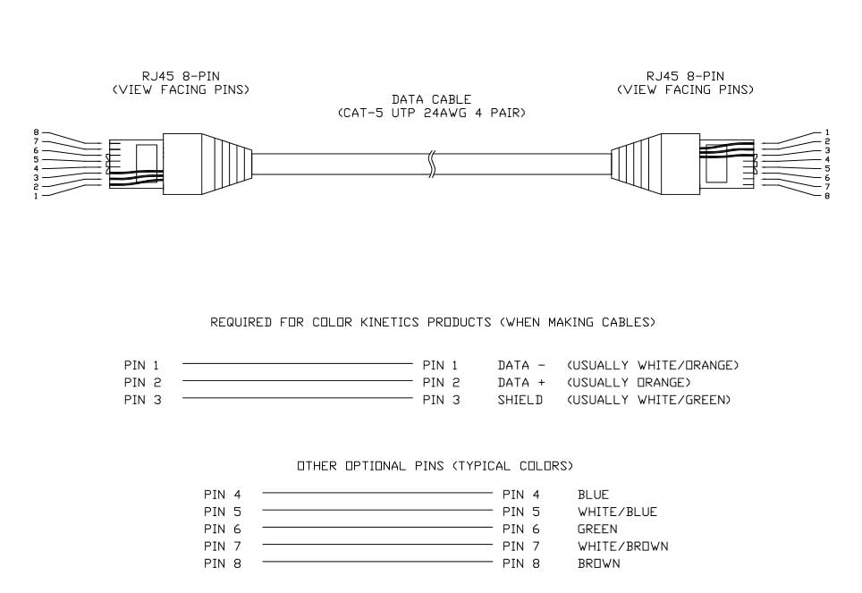
Control RJ45 Port Pin Out Controller Circuit
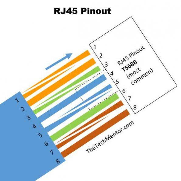
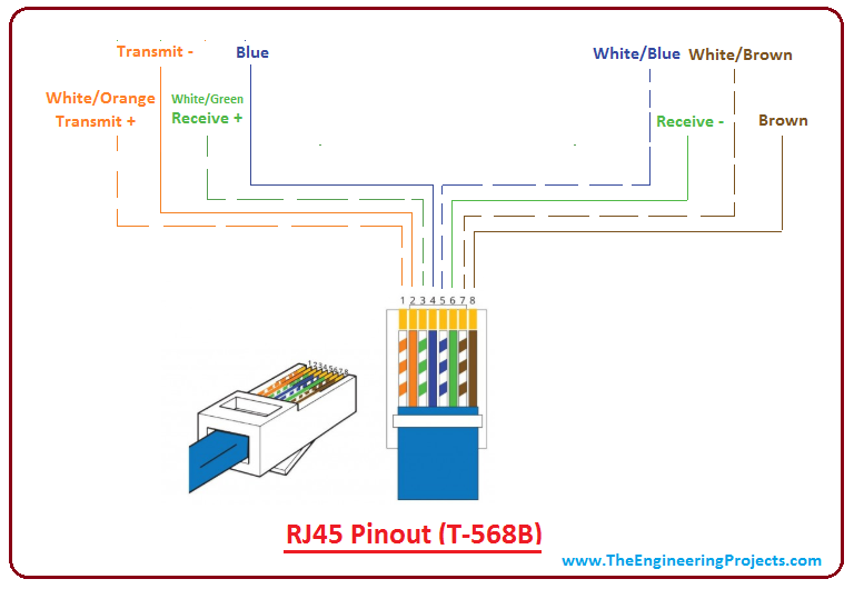
This RJ 45 pin diagram (T-568B) shows everything you need in one handy image, with iso-view and RJ45 color order, suitable for printing quite large. I like this pinout diagram because it shows everything you need. It includes an isometric view and pin-color order table, all in one large diagram.

RJ45 Pinout
The RJ45 connector is a modular 8P8C connector used for terminating Cat5, Cat5e, Cat6, and Cat7 twisted-pair cables. RJ45 pinout is a specific wire arrangement that illustrates how the wires of Ethernet cables are terminated. RJ45 connectors have multiple pinout options, including straight-through, rollover, crossover, loopback, and T1.
Easy RJ45 Wiring (with RJ45 pinout diagram, steps and video)
The following diagram shows pinout of RJ45 jack and the connector, as well as two common color codes of the wires (T568A and T568B). RJ45 PIN DESIGNATIONS A compliant PSE may provide power only via valid pairsets specified by IEEE802.3 standards (the PoE systems that use standards other than IEEE still use the same IEEE pinout).
RJ45 Connector Pinout Diagram Warehouse Cables
As with any modular connector, RJ45 connectors offer a variety of benefits, such as low cost, solderless assembly of connector and wiring, quick production of custom cables, simple insertion and removal, easy field assembly with simple tooling, and the ability to customize cables on-site.
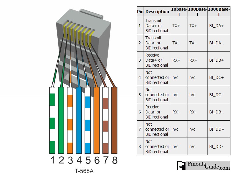
10/100BaseT ( RJ45) connector pinout diagram pinouts.ru
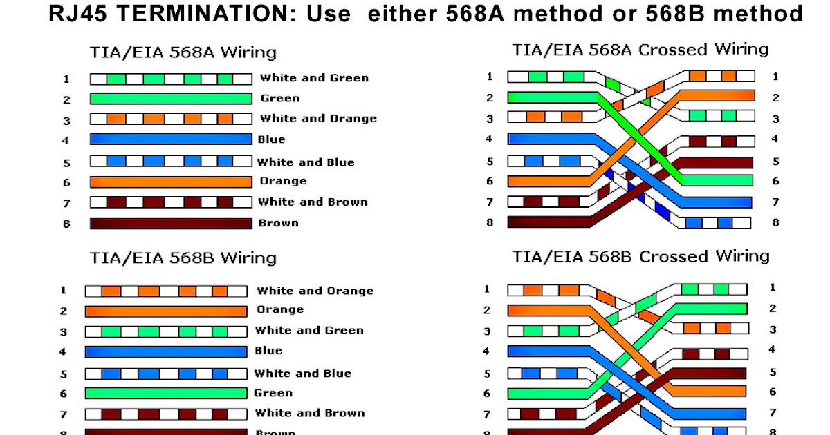
RJ45 ethernet connection pinout There are two standards for RJ45 cable wiring: EIA/TIA 568A and EIA/TIA 568B. Both are correct. You may use either of them to crimp the Ethernet RJ45 net connection cable.
How to make RJ45 cable Inst Tools
The RJ 45 pinout is a result of the TIA standardization of cabling between commercial buildings. Many telecommunications, data, audio and other industries have adopted this protocol. The EIA/TIA and over 60 additional organizations contributed to this new standard.
Rj45 Pinout Wiring Diagram
Get up to date on the wiring of an Ethernet cable with our RJ45 connector pinout diagram at Warehouse Cables! We're here to help you understand your wires.
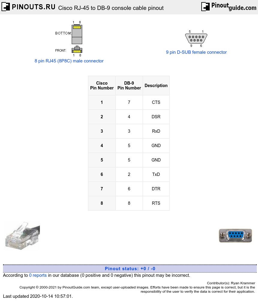
Cisco RJ45 to DB9 console cable pinout diagram
The RJ45 connector, also known as the Registered Jack-45 connector, is a crucial part that helps connect computers to local area networks (LANs) and other devices.First designed for telephones, the RJ45 connector has grown to become a standard way to connect many things. Furthermore, the RJ45 connector employs an eight-pin modular jack called the RJ45 pinout.

RJ45 Pinout Diagram, Colour Code, Wiring Diagram(cat 6,7,5e) ETechnoG
RJ stands for Registered Jack and the number 45 refers to a specific physical connector that has eight conductors. A trend in designing network elements and devices is to build modularity into them.
Introduction to RJ45 The Engineering Projects
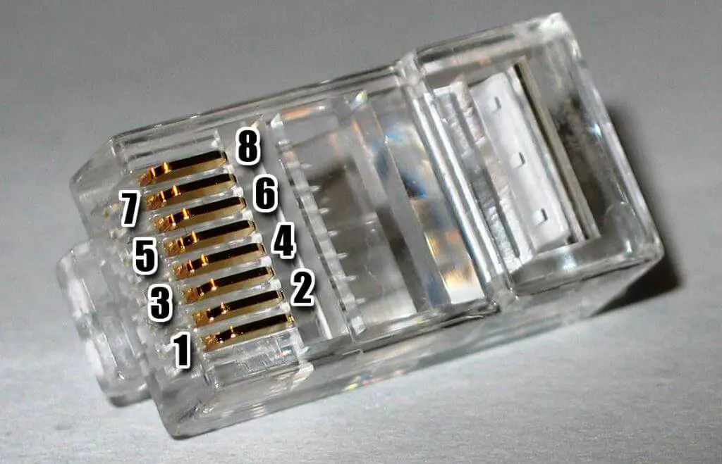
December 24, 2016 CCNA RJ45 (Registered Jack 45) is the connector that consists of 8 metal connection point. RJ45 pinout diagram shows the way how that connector provides communication with network devices. RJ45 exists at the end of the ethernet cables that is used for internetwork communication.
Cable Pinout information for RJ45 cables Knowledgebase
This video lecture Jim Gibson from www.Cablesupply.com explains the pins and wiring in Ethernet cables http://cablesupply.com/cat5e-cat6-booted-patch-cords-m.

Rj45 Wiring Scheme
RJ45 cable pinout with color code The connector of Ethernet cable has two standards, i.e., T568A and T568B. Both these standards have the same number and color of wires. The only difference lies in the positions of green and orange wires. Let's discuss T568A and T568B pinout standards in detail. RJ45 (T-568A) color code and pinout

How to Setup an RJ45 Pinout? Anderson Corporation
RJ45 connector pinout. An RJ45 connector is connected with an RJ45 cable (Ethernet cable). Based on the standard of RJ45 cable, it can either be T568A or T568B. RJ45 T-568A pinout. RJ-45 T568A connector pinout. As shown in the figure above, T-568A consists of 8 wires. The order of wiring is White-Green, Green, White-Orange, Blue, White-Blue.
Cable Pinout information for RJ45 cables Knowledgebase
RJ-45 Ethernet Cable Pinout. Twisted Pair Cables use RJ-45 (Registered Jack) connector. Coming to the main point of this article, the Ethernet Pinout, the TIA/EIA color-coded the four twisted pairs cables as per the TIA/EIA - T568-A or TIA/EIA - T568-B standard. The following table shows the cable colors in each standard.
Color codes for rj45 An ultimate guide on RJ45 wiring colors
RJ45 serial port pinout updated on 22 Mar 2018 10:18 AM. DOCUMENT RESOURCES.

RJ45 Pinout
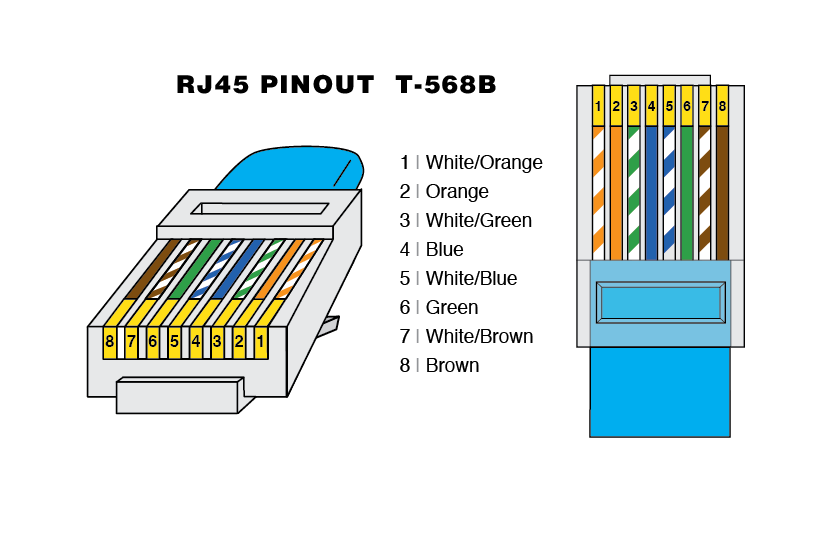
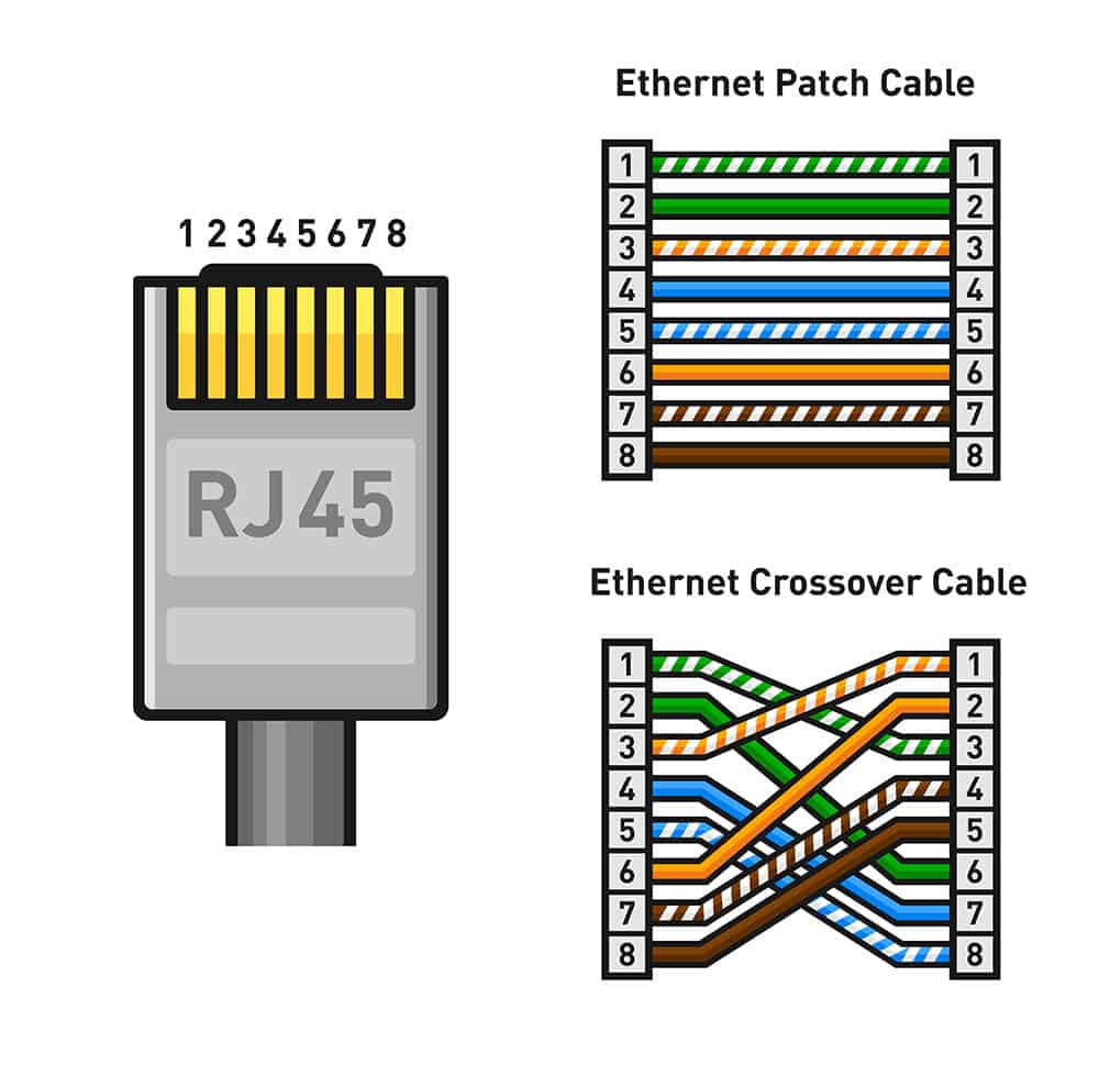
RJ45 Connector Pinout and Color Code The pinout, or the arrangement of pins, in an RJ45 connector follows a standardized color code, known as T568A or T568B. The T568A configuration follows the following color sequence from left to right when the connector's tab is facing down and the cable is running away from you: Green-White, Green, Orange-White, Blue, Blue-White, Orange, Brown-White, Brown.